|
|
|
First, fellow MiataTurbo.net user musanovic has finally stepped up and documented a similar procedure to mine for the later, MAF-equipped cars. If this sounds like you, head on over to http://www.rpaperformance.com/miatamaf.html and check it out.
Now, for the rest of us, maybe you’re running a VTA bypass valve and you’re tired of going mega-rich during shifts. Maybe your AFM is just about dead after 16 years of abuse and you can’t stomach $400 for a new one. Maybe you’re just envious of all those FM Link users bragging about their setup. Whatever the reason, here is the answer.
First thing you are going to need is an eManage Ultimate and the official Greddy 4-bar pressure sensor, with harness. Yes, I know... That stupid Greddy MAP sensor is expensive and we don’t actually need 4-bar range. Trust me, I tried this months ago when I was running a GM 2-bar sensor and just couldn’t make it work right. Fortunately that sensor got re-used in my water injection system so it’s not a total loss.
The second thing you need is a map. This is the part that took me a while. Let me say right now that the Data Sampling Map feature in the new 2.0 build of the EMU software is completely and utterly worthless. In fact, it’s worse than worthless, it’s downright misleading, with a predilection towards evil. The Sampling Map logs only the most recent value for each cell, but an internal combustion engine is an erratic critter. What we need to do this right is a good average of a broad range of data samples for each cell, as we’ll see in a minute.
I logged about a week’s worth of driving, capturing RPM, pressure, and AFM(v). Tried to get everything- steady cruise, lugging the engine, full and part-throttle trips to visit Mr. Rev Limiter... Then, I exported the logs to MS Excel. That bit is actually easy- in the EMU logger software, you do a “Save As” and select data type “Text File.” This gives you a nice tab-delimited file containing only those parameters you’ve checked for display, which you can then import into Excel and sort as needed. I wound up with nearly 300,000 lines of log data, which due to the way Excel handles things had to be split into six worksheets.
Here’s a brief example showing the data for one second of engine operation at light cruise. Sample_Data.Txt
So first, I sorted the raw data by RPM and separated it out so that each worksheet covered about a 1000 RPM range. There was less data in the higher RPM ranges, so those worksheets spanned a broader area. It’s important to demarcate the worksheets at a spot that’s not going to get used to build a map cell, I chose to split them at points of x750. So one sheet was 500-1750, the next 1750-2750, etc.
Next, I sorted each worksheet by PSI, and then located those pressures that corresponded to cell centers. I selected a range of pressures around each center (for instance, all data from -7.8 PSI to -8.2 PSI for the -8.0 PSI cell) and sorted that whole range by RPM. Next, I selected an RPM range of about +/- 100 to 200 RPM around each cell center to analyze. So, the 2500 RPM cells in the lower pressure areas (where data was plentiful) were based on data from 2400-2600, but as I got to the higher pressures (where data was more scarce) I opened up the range to 2300-2700 in order to capture more datapoints.
I found the raw AFM data to be amazingly erratic, which was something of a surprise. Looking more closely at the original logs confirmed that the AFM spends a lot of time bouncing around on throttle transitions before it settles into a stable value. This was especially true during shifts under boost, where that darn flapper actually seems to be bouncing off the stops at both ends of the meter housing. So I wound up drawing a chart for each group of data, which helped me to visualize it and manually remove those values that I felt were erroneous. Here’s an example showing the data that produced the -3.6PSI @ 2500 RPM cell. You can see that the trend for this cell tended to be about 1.01 volts, and the mean average of all the data for that range was 1.009, so 1.01 is what I entered into the map.
Nearly two hundred charts in all, since we’re dealing with a 16x16 map. Why not 256? Well, I obviously didn’t have any data for some engine conditions, like 12PSI at 500 RPM, or anything actually at or above 7500 RPM, so a lot of the map wound up being extrapolated. Once I’d run out of real data, I plotted the resulting map on another chart and used that to smooth out some of the lines by hand, and extend the data out to the left and right to fill the holes. I wound up with what I feel is a pretty accurate plot of the AFM readings for our engine:
Next order of business: road test! I enabled the Airflow Output Map under parameters and filled the data I’d gathered into the airflow map. I decided to leave the AFM in the car for the moment, so I could log true AFM vs. emulated AFM to see how close my guesswork had been. I immediately noticed that there were some discrepancies- for instance, I found that the output of the AFM for a given cell is different depending on whether you’re accelerating or decelerating. My original data hadn’t accounted for this unexpected condition.
So I spent the next few days analyzing logs and hand-tuning a lot of the cells to optimize the output for acceleration and steady-cruise conditions rather than deceleration. Make a change, go for a test drive. Make another change, go for another test drive. A lot of that... Most of the error seemed to occur between 1000 RPM and 4000 RPM, from -12.3 PSI to -8 PSI. By the end, I’d finally gotten it pretty close. Here’s a screenshot of actual AFM input (red) vs. MAP-based AFM output (blue) showing a few seconds' worth of maneuvering through traffic. Remember that this is inverted relative to load- a rising line is decreasing airflow, a falling line is increasing airflow:
Not too shabby. Here’s another one showing a close-up of a shift under boost. Notice how the real AFM signal is bouncing all over the place, but the MAP-based signal just rises and falls cleanly.
Once all the hand-tuning was done, the final product came out looking like this:
Also, here’s the data in tab-delimited format for those who want to import it directly: AFM_MAP.TXT
During this time, I also noticed that I’d developed a slight hesitation getting into the throttle from idle, or mashing the throttle during light cruise. I couldn't really explain why this was, but I decided to tinker with the EMU’s accel enrichment map. This was a bit tough since I don’t have a real analog TPS, but I do still have my MAP sensor tee-d into the TPS input, since I’d been using this to trigger the A/F autotune. So I enabled accel enrichment in the Parameters screen and started tinkering with it.
This part was pure guesswork, but in the end I found the following data to more or less mitigate the problem. Also note that my Throttle parameters tab is set to “normal” and manually scaled for 0.50(min) to 2.50(max). If yours is at 0-5V, or if you have selected automatic, these data will be wrong for you:
Obviously those of you who have installed true analog TPSs will be able to solve this problem far more elegantly.
So once that was all said and done, the next order of business was to actually remove the airflow meter. Now, even though we’ve taken care of the AFM signal itself there are two other things we need to handle. Inside the AFM is a switch that turns the fuel pump on, and a temperature sensor as well.
Since I needed all this to be easily removable, hacking up my AFM was not an option, nor was cutting too deeply into the car’s wiring harness. I searched eBay and found a 1.6 Miata AFM for $7. It was listed as “broken” because some poor sap had removed the two screws from the connector and thus destroyed the internal circuit board. But since I was planning to do that anyway, it was perfect. If you find yourself having to demolish a perfectly good AFM for this project, I suggest you buy one from an RX-7, so as not to deplete the world’s finite and dwindling supply of operational Miata parts. Oooh, somebody’s gonna flame me for that. ;)
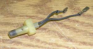
Here’s the AFM opened up. To get to the temp sensor you first need to remove the connector from the outside. Yes, you’re going to break the fusion welds to the circuit board, just like everybody has always told you not to. Try not to damage the leads coming off the connector, as we’re going to re-use it. Just remove the screws holding the spring mechanism and the circuit board in, then pull the sensor straight out.
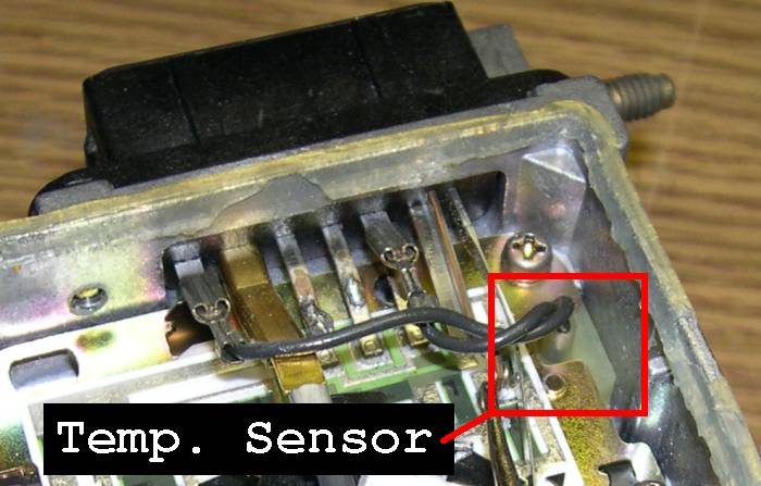
And here’s the sensor removed. Later on in the process I snipped those terminals off and installed some regular bullet connectors. Don’t worry about which wire is which, this is a resistor, and resistors are not polarity sensitive.
Ok, now on to the connector. We need to have a way to attach the temp sensor to it, and we also need to deal with the fuel pump. Here’s what the connector looks like once it’s out. I’ve highlighted the terminals for the temp sensor in green, and for the fuel pump switch in red (with apologies to color-blind readers).
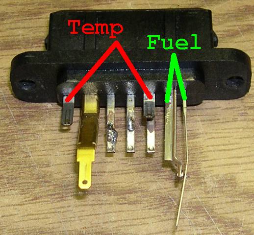
Notice how the fuel pump contacts form a normally-closed switch. When there is no airflow through the system and the flapper is fully closed, there's a little rod on the spring mechanism that forces this switch open. When air starts to move through the system and the flapper begins to open, the switch is allowed to close, thus energizing the fuel pump relay. (There's also a wire in the starting circuit that energizes the relay independant of this switch for when you're cranking the engine.)
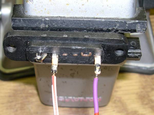
I chose to use a dremel to cut off the un-needed contacts. In retrospect I should have left them on and just trimmed them down a bit, since I’d later epoxy the connector and this would have given me a stronger bond, but alas. Anyway, I soldered two wires to the temp sensor connectors, and just soldered the two fuel pump leads together. In doing so I bypassed an important safety feature which is designed to shut off the fuel pump in the event of a serious collision. I should have connected wires to these and run them to an RPM-based switched output of the EMU, but the EMU was already installed and I got lazy.
The leads themselves had a thin plating on them which initially prevented the solder from sticking. I used the dremel again to remove this plating and roughen up the surface of the leads so that I could get good solder flow onto them.
Note that in this picture the connector has been turned upside-down relative to the last picture.
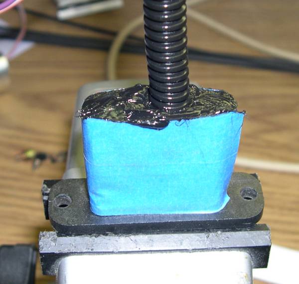
Lastly, I created a form around the connector base out of blue masking tape, slid a piece of split tubing over the wires, and filled the whole thing with black RTV. Two-part plastic epoxy would have been a better choice, but I was all out.
So that’s pretty much it. To finish off the system I cut a piece of 2.5” exhaust pipe to fill the space where the AFM used to be, and installed the temp sensor in it, again using black RTV. This probably would have been a good place for JB-Weld, but again, none sitting on the shelf when I needed it.
I contemplated installing the temp sensor downstream of the turbo and intercooler, but decided against it. Encapsulated sensors like this are very slow to respond. It wouldn’t be fast enough to detect the quick temperature spike when getting on-boost, and by the time it finally did start to show a rise in temperature I’d already be out of boost and back down to normal temps. So best to let it just sit there tracking under-hood temps and worry about boost in the fuel and ignition maps.
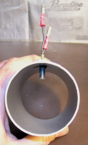
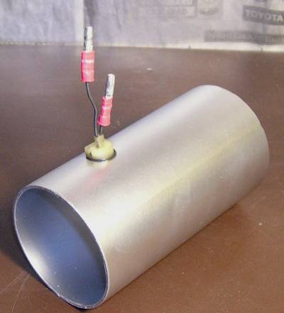
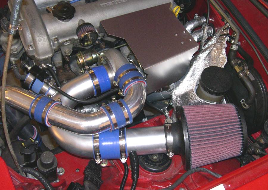
And here’s the finished product. The new pipe goes right where the AFM used to, and it plugs right into the factory AFM connector. This is great for those people who need to un-modify their car on a semi-annual basis for emissions inspections. In the closet I have the whole assembly of the stock Greddy intake elbow with the AFM and foam air filter completely assembled and ready to drop into the car as one piece.
Questions and comments are welcome. You can reach me over at MiataTurbo.net where I go by the username Joe Perez. If you're not already a member there you should be.
He has been knifed in a London subway, tear-gassed by the Michigan State Police, narrowly avoided a terrorist bomb at a theater in Tel-Aviv, and was once denied service at a Howard Johnson's restaurant.
In his spare time, he enjoys channeling the spirits of former U.S. Presidents Nixon and Eisenhower, who report that they are enjoying the afterlife, and frequently participate in racquetball matches with Cliff Burton, the original bass player for Metallica.
In short, nothing you can say or do will surprise him, so don't be afraid to ask what may, upon inadequate reflection, seem to be stupid questions.